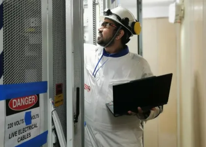





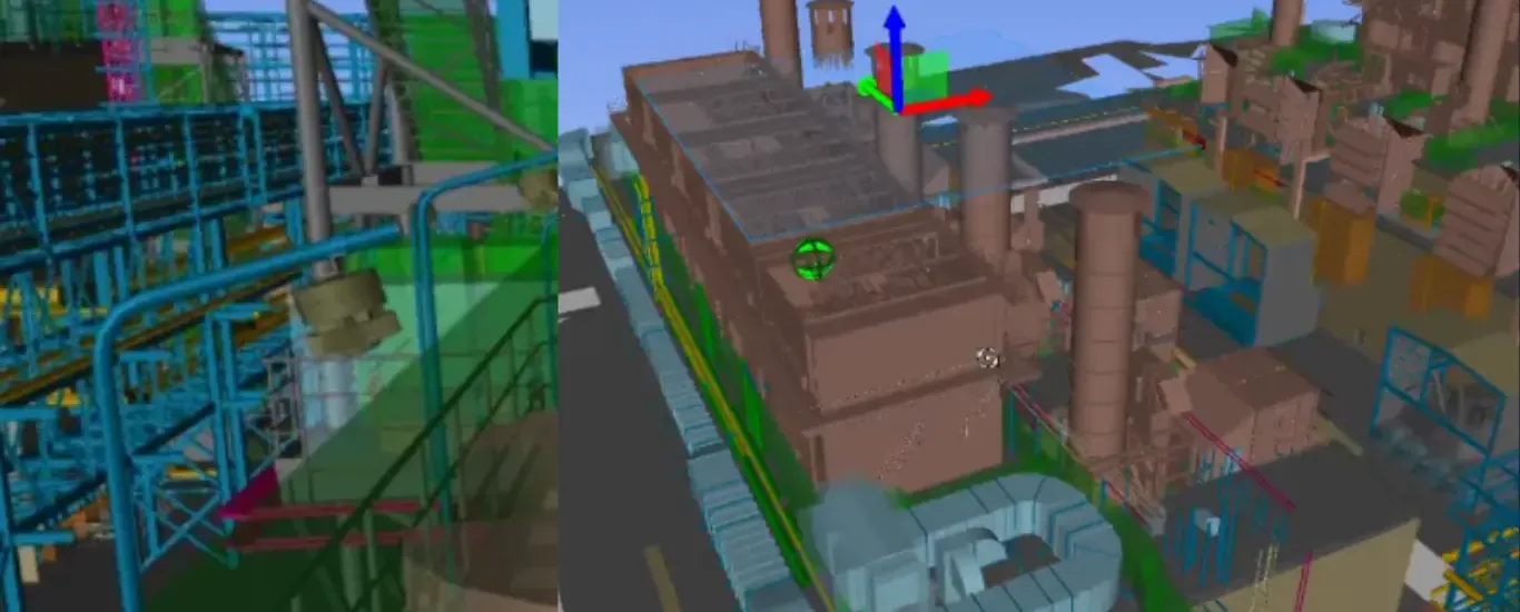
Detailed telecom engineering drawings determine how systems like PAGA system, CCTV network, radio system, fibre-optic network or other communication system can be installed as it’s the detailed drawings are a critical stage of the process.
These detailed drawings show where equipment will be installed, how systems will connect, where cables will run, how equipment will be interconnected, and how the completed system should function.
For complex facilities such as FPSOs, offshore platforms, vessels and hazardous-area industrial facilities, accurate telecom drawings play a critical role. In particular, engineers must carefully coordinate available space, cable routing, equipment locations, environmental conditions and existing infrastructure to create a practical and reliable design.
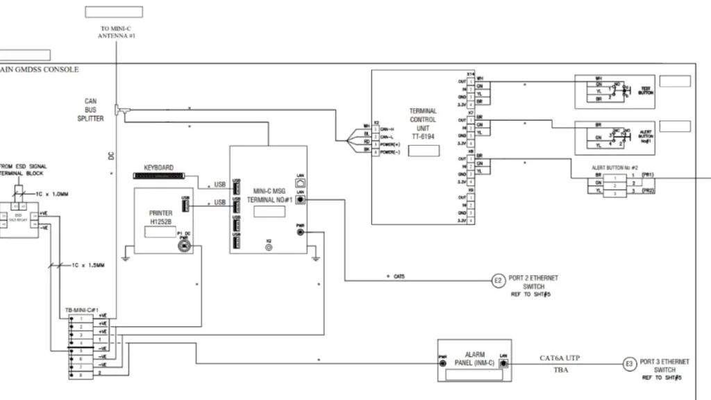
What Are Telecom Engineering Drawings?
Telecom engineering drawings define how telecommunication systems should be designed, installed and integrated.
They show the proposed telecom infrastructure in detail, including equipment locations, cable routes, connections, network architecture, racks, cabinets, junction boxes, antennas and other system components.
Depending on the project, a telecom drawing package may include:
- Telecom system block diagrams
- Equipment layout drawings
- Cable routing layouts
- Cable schedules
- Rack elevation drawings
- Wiring and termination diagrams
- Network architecture diagrams
- Fibre-optic diagrams
- Antenna and radio layouts
- Equipment room layouts
- Earthing and bonding
- Junction box and termination details
- Installation details
- As-built drawings
- layouts
The requirements of the drawing may chaage according to the project, client specification & systems involved etc.
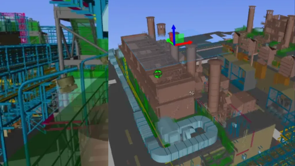
Why Are Detailed Telecom Drawings Important?
A telecom system can involve hundreds or even thousands of individual connections. Without properly coordinated drawings, it becomes difficult for engineering, procurement, construction and commissioning teams to work from the same information.
A detailed drawing package helps teams understand:
What needs to be installed?
Equipment, cabinets, junction boxes, antennas, cables and associated components can be clearly identified.
Where does it need to be installed?
Equipment locations and cable routes can be coordinated with the physical facility.
How does everything connect?
System architecture, wiring and termination drawings show how individual components connect.
What cable is required?
Cable schedules identify cable types, sizes, origins, destinations and other relevant information.
How will the system be commissioned and maintained?
Accurate documentation provides a reference for testing, troubleshooting, future modifications and maintenance.
In other words, telecom engineering drawings turn a system concept into something that can actually be procured, installed, tested and maintained.
Key Types of Telecom Engineering Drawings
A telecom system can involve hundreds or even thousands of individual connections. Properly coordinated drawings help engineering, procurement, construction and commissioning teams work from the same information.
A detailed drawing package helps teams understand:
Telecom System Block Diagram
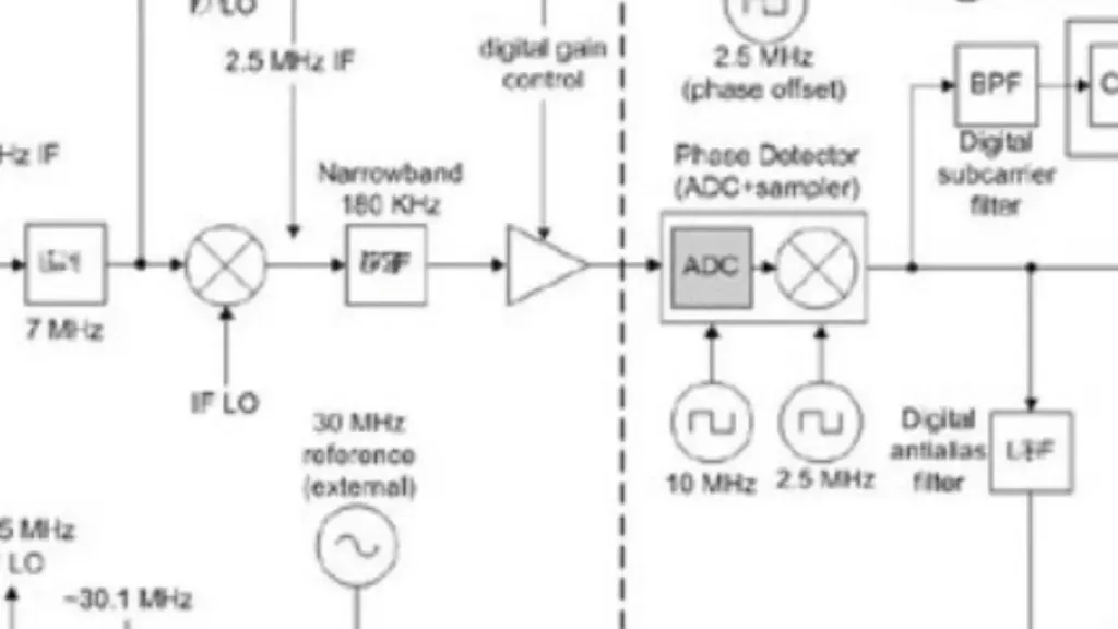
System block diagram provides a high-level view of how the different components of a telecom system are connected.
Diagrams can show connections between multiple telecom systems, buildings, offshore modules or network segments.
Telecom Equipment Layout
Equipment layout shows the physical location of telecom equipment within a facility.
These need to be coordinated with other engineering disciplines to ensure that sufficient space, access, cable routes, power and environmental requirements are available.
Cable Routing Drawings
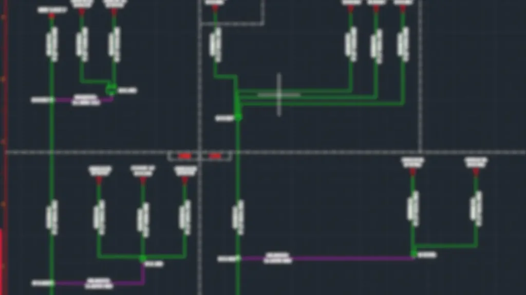
How telecom cables travel through a facility is shown from cable routing drawinga
In offshore and brownfield projects, engineers must carefully plan the routes around existing cable trays and pathways, which may already have limited space or heavy congestion.
Rack Elevation Drawings
Rack elevation shows the physical arrangement of equipment inside a telecom rack or cabinet.
It help the fabrication and installation teams understand exactly how equipment should be arranged.
They also provide a useful reference during maintenance and future system upgrades.
Network Architecture Drawings
Modern telecom systems increasingly rely on IP-based networks.
These drawings help engineering and commissioning teams understand both the physical and logical relationships between network components.
Antenna and Radio System Drawings
Radio communication systems require careful consideration of antenna locations, cable routes and equipment connections.
Offshore and industrial facilities, antenna placement may need to be coordinated with structures, equipment, hazardous areas and other systems.
Telecom Cable Schedule
A cable schedule provides detailed information about each cable in a telecom system.
Helps connects information across different drawings and helps engineering and installation teams track each cable from its source to its destination.
Typical cable schedule identifies the cable type, size, source, destination, route and other installation details.
Wiring and Termination Diagrams
Wiring diagrams provide detailed information about how equipment and components are electrically or optically interconnected.
For systems such as PAGA, emergency voice communication, radio and other critical communication systems, detailed wiring information is essential for installation and testing
What Information Should Detailed Telecom Drawings Contain?
Every project has its own requirements, but a well-developed telecom drawing package should give construction and commissioning teams the information they need to install and verify the system. This typically includes:
Equipment information
Cable information
Physical installation information
System information
Documentation information
Objective is not simply to create a visually detailed drawing. The drawing must contain the engineering information required to build and verify the system.
Get the Right Team of experts!
Detailed telecom engineering drawings require more than drafting. They require engineering expertise, specification knowledge and industry experience.
At Vivo Asia, our expert telecom engineering team understands client and industry specifications and develops detailed drawings for oil & gas, offshore, maritime and industrial projects.
With a state-of-the-art drawing facility and experienced engineers, we deliver accurate, coordinated and practical engineering documentation—from system layouts and cable routing to rack elevations, schematics and network drawings.
Request a quotation from our sales team contact@vivoasia.com for your projects next detailed telecom engineering drawings.